

Do’s and don’t of cam follower installation
If you have cam follower bearings installed in your facility, then maintaining a great performance from those bearings will be something you are interested in. You can help obtain great bearing performance if you keep some particulars in mind during installation.
If you have cam follower bearings installed in your facility, then maintaining a great performance from those bearings will be something you are interested in. You can help obtain great bearing performance if you keep some particulars in mind during installation.
DO
1. Do install the oil hole plug in applications where the bearing will not be re-lubricated. Because it’s an optional part of the installation, in applications where re-lubrication will be performed, the user may be inclined to discard the oil hole plug. Installing the plug helps protect the bearing from contaminant entry, such as fine grit, metal dust, or liquids, promoting longer life. Longer life means less down time and fewer bearing replacements.
2. Using a press fit on the stud helps to create proper support of the stud in application; it can be used when installing stud-type cam followers. Press fitting is when you have an interference fit requiring you to apply pressure on the stud end face of the bearing. Be sure to apply the pressure through the stud end face, preferably using an arbor press.
3. Specifically, for the yoke type bearings: please do back up the bearing’s end plates. Yoke type bearings require a housing to support the end plates. Do not shirk on keeping the end plates supported. Keeping those end plates supported maintains the bearing’s proper assembly in operation, and helps avoid premature application breakdown and possible injury due to disassembly. It will also prevent unnecessary bearing replacement and unnecessary cost.
4. You may know the stud type cam followers require a certain amount of torque applied to the locking nuts, in order to adequately lock the stud in place. Overtorque can cause bearing damage and undertorque can allow bearing disassembly. Excessive torque can result in stud elongation or fracture. Inadequate torque can allow the cam follower to become disassembled from the housing. Keeping the proper torque as shown in the bearing’s chart will maintain clamping pressure adequate to lock the stud in place, keeping the bearing in its intended position.
5. Some applications need little maintenance, such as those involving slower speeds, fairly clean environments and ambient temperatures. However, re-lubrication becomes more crucial as application speed, temperature, or contamination levels increase. Do regularly inspect and as necessary re-lubricate your bearings. Keeping your bearings in top condition maximizes their operational performance and life. Regular check-ins are also a good opportunity to inspect the state of their installation and working environment.
DO NOT
1. During installation, do not hammer directly on the bearing! Doing this can cause damage to your bearing or injury to those involved.
2. Don’t neglect your bearings. I don’t need to tell you that negligence can result in permanent damage and shorten operating life. In short, you’re wasting money.
Darbar Company is Pakistan's leading supplier in Cam Followers. You can send your particular inquiries by filling out this form
Original article can be found in the February issue of Bearing-News Magazine

How To Prevent Pulley Slippage
There are a variety of methods used to attach pulleys to shafts. Knowing the advantages and disadvantages of each one will help you make a better choice when installing drive components into your assembly. Using the appropriate method for your application can go a long way in preventing damage and possible equipment failure. Consideration should also be given to field service needs.
There are a variety of methods used to attach pulleys to shafts. Knowing the advantages and disadvantages of each one will help you make a better choice when installing drive components into your assembly. Using the appropriate method for your application can go a long way in preventing damage and possible equipment failure. Consideration should also be given to field service needs.
Controlled tolerances between the shaft and pulley prevent slipping and can be achieved through various mounting devices or fastening methods. Type of connections between shaft and pulley:
- Set-screw
- Fairloc
- Press-fit
- Shaft-lock
- Shaft extenders
- Clamp
Structure: advantages and disadvantages of each:
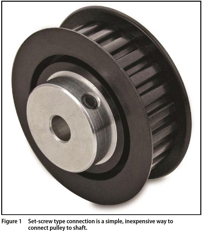
Set-screw type connection is a simple, in expensive way to connect a pulley to a shaft. The pulley requires an additional extension (Hub) on which, perpendicular to the direction of the shaft a hole or holes are drilled and tapped.
Drilling and tapping can be performed on any type of material the pulley is made of, most common are aluminum, stainless steel, steel, and plastics, with a metal or reinforced hub.
Disadvantages: require additional axial space because of the hub's projection; torque transmission is limited in comparison to press-fit and shaft lock types. In addition, different types of set screw tips can damage the surface of the shaft.
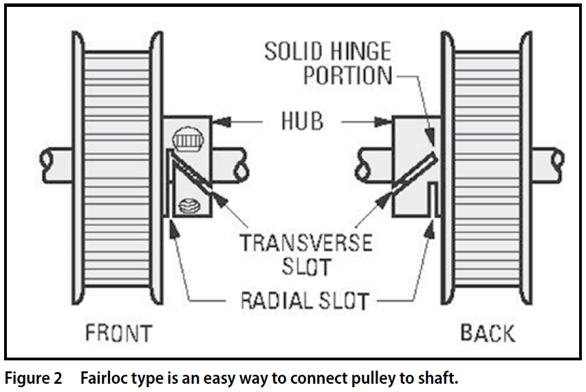
Fairloc Type is an easy way to connect the pulley to the shaft.
Two slots are machined into the hub - one oriented radially, the other angularly - to create a transverse wedge which remains attached to the solid portion of the hub on one side. The resultant cantilevered clamping section has a tapped hole to accept a cap screw which passes through a clearance hole in the solid portion of the hub, and into a threaded hole in the transverse wedge section. As the screw is tightened, the cantilevered section clamps the shaft securely.
The compact, self-contained design reduces misalignment and can be tightened and released repeatedly without marring the shaft. Produced in stainless steel, aluminum and brass, it is well suited for applications that require moderate torque and speed. For optimal performance Fairloc hubs require controlled tolerances between the shaft and pulley (suggested clearance fit .0001"/.0008"). For high-torque/high-speed applications, shaft locks are a better option.
Press-fit type, especially for metal on metal, is a good option for applications requiring tight concentricity/runout. This method performs well in low/moderate torque (20-30 lbs x in.) applications, even for high rotational speeds. Good for devices where space constraint is a concern.
Disadvantages: Requires very precise tolerances on the bore of the pulley and on the pilot surface of the shaft. Not all combinations of materials provide the same torque capacity of the press-fit
Shaft-lock type is a very robust way to connect a pulley to a shaft; good for high-speed applications as well. It is recommended for mechanisms where axial space is of concern; doesn't require extremely precise tolerances on the pilot surfaces. These devices are made of various types of metals (steel is preferred).

Disadvantages: a more expensive option (requires additional component, the shaft-lock). Some of the shaft-lock devices, especially the heavy duty ones, are not easily installed and even more difficult to uninstall.
Shaft Extenders are used where large axial distances between components need to be compensated. When produced in stainless steel they provide the best performance for high-torque (70-80 lbs x in.) and high-speed applications.
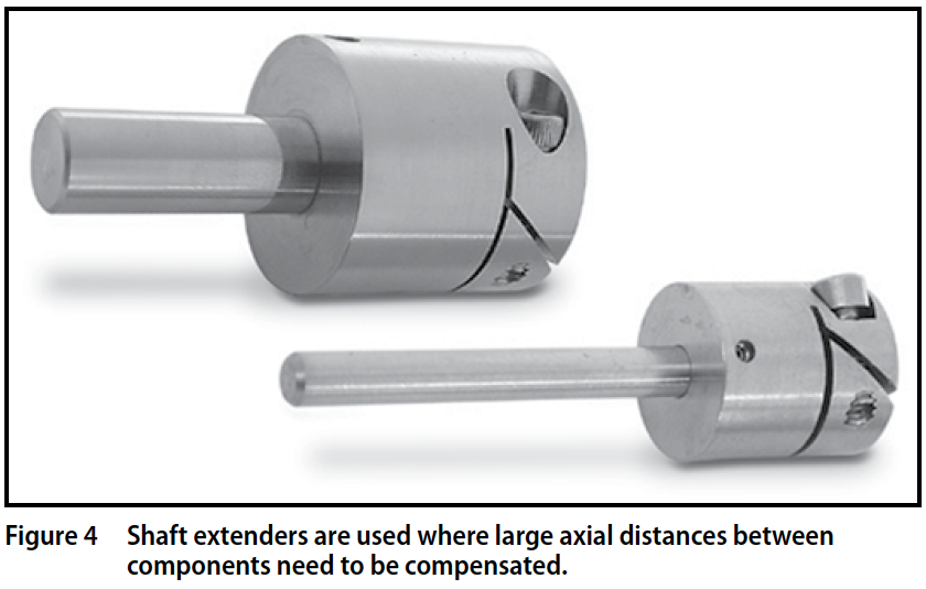
Disadvantages: requires high precision shafting and very tight concentricity bore and the shaft O.D.
Clamp type requires additional clamp to connect a split hub pulley and a shaft. Clamps come in a variety of configurations; balanced clamps are used for high-torque applications.
Disadvantages: additional component - the clamp. Requires controlled tolerances on pilot surfaces, some of the constructions are difficult to assemble. Usage of clamps has declined as easier to use connecting methods have been developed.
Applications:
- Set-screw: in mechanisms used for shop manual tools
- Fairloc: aerospace, avionics, medical, printing, scanning devices
- Shaft-lock: power tools, oil industry
- Shaft extenders: drilling devices
When attaching the pulley to a shaft you have a number of choices; one method may work better in your application than another. It is important to have a basic understanding of your drive system and keep the following points in mind: torque, speed requirements, accessibility, material and cost.
Darbar Company is Pakistan's leading Power Transmission Solution provider, mainly specializing in Bearings, Roller Chains and Timing Belts. Give us a call to find out what products we carry.
The original article can be found at the Power Transmission Engineering blog here

Bearing The Brunt of Earthquakes
According to FEMA study back in 2000, America suffers $4.4 billion in losses due to earthquakes every year. While that’s a drop in the bucked for their $16 trillion plus GDP, it’s still a substantial amount of money, and some people are working on to lessen those losses. One group is Earthquake Protection Systems (EPS), a company that is designing bearings to better protect buildings from earthquake damage.

According to FEMA study back in 2000, America suffers $4.4 billion in losses due to earthquakes every year. While that’s a drop in the bucked for their $16 trillion plus GDP, it’s still a substantial amount of money, and some people are working on to lessen those losses. One group is Earthquake Protection Systems (EPS), a company that is designing bearings to better protect buildings from earthquake damage.
According to EPS Vice President, Dr. Anoop Mokha, standard building regulations are inherently flawed, as they insist that a building be capable of remaining standing during an earthquake, but say little about what state the building needs to be in beyond that. This means that while we’ve gotten pretty good at making sure buildings don’t collapse and hurt people during earthquake, there’s still a high number of buildings that are being crippled and rendered derelict by them. As an example, Mokha pointed to an earthquake that happened in New Zealand in 2010. Only two buildings collapsed during the quake, but the event still left 70 percent of affected buildings so badly damaged that they had to be torn down.
Ever since the company first opened its doors in 1985, EPS has been working to reverse that trend with a product they call a friction pendulum bearing, which is designed to not only keep buildings standing after an earthquake, but to keep them operable and livable.
“What we are doing is allowing engineers and owners to have sustainable structures they can walk in after an earthquake, they have no damage,” Mokha said.
The bearings are designed to absorb excess energy when the force of an earthquake exceeds a building’s acceptable horizontal load and safely dissipate it in the form of motion. This means that when an earthquake’s force would otherwise damage a building, the bearings allow the building’s foundation to physically move back and forth like a pendulum, finding an outlet to expend otherwise damaging levels of force.

EPS’s newest product, the Triple Pendulum Bearing, takes it a step further, with three different bearings in a single product all designed to resist different magnitudes of earthquakes, the bearings activate sequentially, so that only one bearing is active at any given time, but each bearing is ideally suited to different magnitude earthquakes, and when one bearing’s ability to resist the earthquake is overloaded, the next bearing immediately takes over.
“If the earthquake is weak, the bearing is weak,” Mokha said. “If the earthquake gets stronger, the bearing gets stronger.”

According to Mokha, products like Triple Pendulum Bearing are fairly standard in Japam, where earthquakes are a constant hazard, but are still only just catching worldwide as an effective countermeasure for earthquakes. Mokha estimates that previously, only about 10 percent of buildings in the U.S. used pendulum bearing or equivalent product, but that in recent years, that number may have risen as high as 15 or 20 percent and is still growing.
“What Elon Musk did with the electric car in the automotive industry, and now everyone is realizing the benefits… I believe we have crossed that threshold now, where people are realizing the benefits,” Mikha said.
You can contact Earthquake Protection Systems Directly by visiting their website: www.earthquakeprotection.com
Original article available at Power Transmission Engineering (be sure to subscribe for more industry insights): http://bit.ly/2m4lBe2

Bearing Research: Going To The Atomic Scale
This article provides insight into the four main lines of research through modelling at SKF: bearing steel, fatigue mechanisms, polymer design and tribology.
In the past few years SKF has been expanding its knowledge with the atomic scale simulation methods such as DFT, MD, and DPD, to understand how materials behave in its products. This has enabled and will continue to enable SKF to innovate and cope with ever-increasing technological challenges by ensuring that every atom is in the place it belongs.
Technology
Imagine if one could become so small that he or she could dive into solid materials and see the structure of the atoms – how the interact, move and respond when external force is applied and how the external temperature influences their properties and changes their structure. If this were possible one could better select, process and design the materials used to manufacture products and machines.
At the SKF Engineering and Research Centre (ERC) in the Netherlands, research is done with the objective of virtually diving into the materials that make up SKF’s products to achieve a better understand of their behavior. This enables SKF to respond to requests from customers, and more importantly, to develop new materials for its products that increase their quality, durability and other specific properties.
In most of the cases, the use of experimental methods is enough to gain sufficient understanding of how external constraints might affect the materials from which products are made and to find preventive and counteractive solutions.
Nevertheless, even with the use of state-of-the-art experimental techniques, it is simply not always possible to get sufficient understanding of the effect that certain phenomena can have on the materials. In addition, in some cases such as with a new material or product that in the design phase, being limited to the use of laboratory test tools is not always time-efficient or cost-effective. This is why computational methods are essential
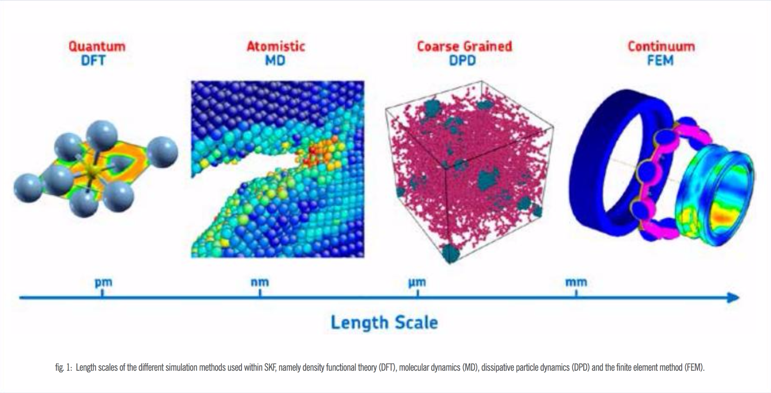
When it comes to mechanical parts, e.g., rolling bearings, most design issues can be worked out using “large scale” simulation techniques, such as the widely used finite element method (FEM). However, some special issues go beyond the capabilities of this modelling tool and require being treated with alternative mesoscopic and microscopic simulation methods.
To get a thorough understanding of SKF’s products and be able to tackle the issues that might have an origin at particular time and length scales, scientists at SKF are constantly developing their know-how in the use and advancement of multi-scale simulation methods. This means that there are different tools (imagine magnifying glasses, all with a different magnifying power) that can be used to understand specific phenomena that determine the behavior of a material in application conditions. This is why the models that are applied at SKF range from quantum mechanical to continuum (fig.1).
The deeper one dives inside the material, the more calculation power and time are needed to make simulations. For this reasons, a high-performance computer cluster with 1,536 processors is being used in SKF facilities.
Currently, there are four major lines of research for which meso- and micro-scale methods are used.
Steel Design
The first line of research is part of the project “MultiHy”, short for Multiscale Modeling of Hydrogen Embrittlement. This project is led by a consortium formed by various European industrial and academic partners and is funded by the European Union. The initial motivation for this project is that there is ample experimental evidence that supports the idea that hydrogen decreases the fatigue life of bearings and structural steels. This effect of hydrogen is known within the technical jargon as hydrogen embrittlement. SKF’s main interest is MultiHy is to be able to predict how hydrogen diffuses into and through bearing steels and, more importantly, to discover how available hydrogen can be trapped and immobilized to neutralize the impact of hydrogen embrittlement on bearing service life.
Such simulations on hydrogen mobility and its effect on fatigue life complement other ongoing research dealing with various sources of hydrogen, e.g., humid environments and possible degradation of lubricants.

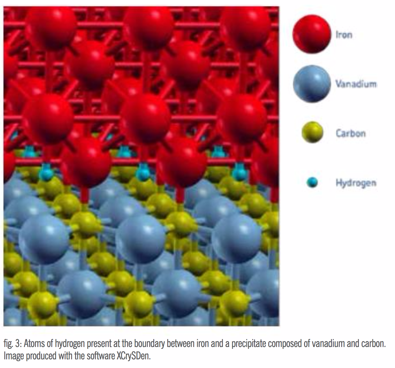
From the atomistic point of view, simulations are being carried out using a computational quantum mechanical modelling method called density functional theory (DFT), which is commonly used to investigate the electronic structure of many-body systems (fig.2). More specifically, simulations are being done to evaluate the mechanical properties and the influence of hydrogen in a new experimental vanadium-containing bearing steel (fig.3) in which hydrogen can be trapped to avoid embrittlement. The results of the MultiHy project can help with the final development of this new steel, so that it can be eventually considered for applications where hydrogen resistance is needed.
Fatigue Mechanisms
The second line of research is aimed at the atomic description of the microstructure of bearing steels and its influence on the behavior of the material when subjected to rolling contact fatigue. For this project, the molecular dynamics (MD) method is being used to study how the atoms move and interact with each other when a crack is initiating and propagating through bearing steel (fig.4). The understanding of this phenomenon will enable SKF to find ways to increase the life and overall performance of SKF products.

Polymer Design
The third application deals with the study of filled rubber materials used in the manufacturing of seals. The overall goal is to identify and quantify the physical phenomena taking place at different scales that influence the quasi-static and dynamic stress-strain behavior of filled rubber. This project is being carried out by SKF in collaboration with scientists from Tsinghua University in China and from the University of Barcelona in Spain.
Dissipative particle dynamics (DPD), a meso-scale simulation tool that enables analysis of the dynamic properties of fluids and polymers (fig.5) at scales that go beyond those that can be treated using MD, is used here. By employing DPD, the effect of various factors, such as the interaction between filler particles and polymer chains and the topological changes in the polymer network in the static and dynamic mechanical behavior of sealing materials, can be fully considered.

Tribology
The final application addresses the lubricated contact between two surfaces, such as that between a rolling element and a raceway in a hybrid bearing. The method used for this work is also MD. The goal is to explain the fundamental differences in friction and wear between steel/steel and steel/ceramic surfaces to improve the performance of hybrid bearings. Also, chemical reactions between the lubricant and the surfaces can be considered.
So far, the modeling has revealed that there are fundamental differences between steel/steel and hybrid contacts related to friction and wear. More importantly, the results have shown that hybrid contacts present lower friction than steel/steel contacts.
This article has been extracted from the latest edition of Bearing-News magazine

Avoid These 3 Mistakes When Lubricating Bearings
Friction is all around us. Without it we would find it very difficult to run, walk, or eve stand on our own two feet. We need friction to drive our cards and fly our airplanes; and we need friction for our motors to drive pumps. But when it comes to our plant machinery, friction is both friend and foe. If part of your job is greasing plant machinery, then you know well the battle against frictional forces that threatens the useful life of rolling element bearings

Friction is all around us. Without it we would find it very difficult to run, walk, or eve stand on our own two feet. We need friction to drive our cards and fly our airplanes; and we need friction for our motors to drive pumps. But when it comes to our plant machinery, friction is both friend and foe. If part of your job is greasing plant machinery, then you know well the battle against frictional forces that threatens the useful life of rolling element bearings
Lubrication of rolling element bearing is one of the most misunderstood and abused tasks in industry. Can it be true that 40% of bearings never live to their engineered life cycle and that bad lubrication practices are the leading cause of this mortality? Bearings depend on grease to reduce friction levels. By avoiding three common mistakes when greasing bearings, you can predict the right time to grease, know how much grease to apply, and be confident in the bearing’s overall health.
Mistake No.1 – Lubricating based on TIME instead of CONDITION
Lubricating a bearing once per week or once per month may seem like a sensible thing to do. After all, performing scheduled maintenance at regular periods is an age-old concept.
Bearings need grease for one reason only; to reduce friction. As long as the lubricant is performing that service well, there should be no need to change it, or add more.
Yet we frequently do, with catastrophic results.
Lubricating a bearing just because your calendar told you “time is up!” is the first mistake. Monitor, measure and trend friction levels with ultrasound to know when it is the right time to grease.
Mistake No.2 – Over and under lubrication
The second mistake we must avoid is adding too much, or not enough grease. Too much grease builds pressure, pushing the rolling elements through the fluid film and against the outer race. The bearing now has to work much harder to push the rolling elements through a mud bog of grease.
The increased friction and pressure from too much grease raises the temperature inside the bearing. Excess heat could decrease the effectiveness of the lubricant causing the oil to separate from the thickener. Not adding enough grease has the same life-shortening effect.
How do we know when just the right amount of grease has been added? By monitoring the friction level with ultrasound as new grease is applied… slowly, one shot at a time. Listen to the bearing and measure the drop in friction as the grease flows in to the bearing. As the decibel level approaches a minimum value and stabilizes pay close attention. Add single shots. Should the decibel level begin to increase slightly, stop! The job is done.

Mistake No.3 – Using a “Listen-Only” ultrasound instrument
Like any job there is a right way and a wrong way to do things. Simply listening to a bearing with an ultrasound device that gives no measurement feedback is a recipe for disaster. The audible feedback alone is too subjective to draw any comparative conclusions. No two people hear the same and there is no way to remember what the bearing sounded like a month ago.
The third mistake is depending solely on subjective ultrasound noise when precise quantifiable data is available. Therefore, always use an ultrasound instrument with digital decibel metering. Better still, use a device that provides multiple condition indicators. Max RMS and Peak dB measurements indicate alarm levels and greasing intervals while Ultrasonic Crest Factor provide insight about the bearing condition in relation to its lubricant. Crest factor helps us differentiate between bearings that need grease and bearings that need to be replaced.
Clear benefits of avoiding the three mistakes
Ultrasound assisted lubrication of plant assets offers significant benefits that calendar-based lubrication cannot. Lubrication serves a primary purpose, which is to create a thin layer of lubricant between rolling and sliding elements that reduces friction. So it makes sense that the best way to determine the lubrication requirement of a machine is to monitor friction levels; not time in service.
Optimizing lubrication of plant machinery with ultrasound will result in a significant reduction in grease consumption. Having an ultrasound program in place will help create a better culture involving cleaner storage practices, sampling, and avoiding mixing greases.
Machines that are properly lubricated require less energy to run. Imagine that reducing the amount of money spent on grease will actually lead to lower energy bills. Machines that consume less electricity run cooler and machines that run cooler have longer life cycles.

Ok, the real reason to optimize bearing lubrication is to extend the life of bearings by making sure they have the right amount of grease, but not too much. When everything is running according to plan lube-techs will spend less time greasing bearings that do not need it. So when counting up the benefits of your ultrasounds program do not forget to add “decreased labor” to the long list.
Finally, by monitoring the condition of your machinery’s lubrication, you are at the same time collecting valuable condition data about the machine itself. Dynamic and static ultrasound data coupled with condition indicators such as Overall RMS, Max RMS, Peak, and Crest Factor are all indicators of bearing health. A practice that does not use this SDT combination is not a real solution when lubricating bearings. Who knew so much good could come from such a simple shift from calendar to condition based maintenance? Now you know.
Darbar Company is Pakistan's leading supplier of Bearings, Timing Belts, and Roller Chains. Our bearings are of the highest quality and require little maintenance. We can guarantee you that our bearings will perform far better than any other on the market, and our prices are very competitive as well.
Original article extracted from Bearing-News magazine